Opening
+--------------------------------------------------------------------+ | | | Transcriber’s Note | | | | In the original book the author used lowercase italic letters and | | lowercase small capitals to label the geometric diagrams. These | | have been here transcribed as lowercase and uppercase italic | | letters respectively (aA). | | | | This file should be read using a font that supports the following | | Unicode characters: | | ∠ angle, ∶ ratio, ∷ proportion, ∴ therefore, ′ prime, and | | ″ double prime. | | | +--------------------------------------------------------------------+
+----------------------------------+ | | | Library Edition | | | +----------------------------------+ | | | | | THE COMPLETE WORKS | | OF | | JOHN RUSKIN | | | | | | ELEMENTS OF DRAWING AND | | PERSPECTIVE | | THE TWO PATHS | | UNTO THIS LAST | | MUNERA PULVERIS | | SESAME AND LILIES | | ETHICS OF THE DUST | | | | | +----------------------------------+ | NATIONAL LIBRARY ASSOCIATION | | NEW YORK CHICAGO | +----------------------------------+
THE ELEMENTS OF PERSPECTIVE
ARRANGED FOR THE USE OF SCHOOLS
AND INTENDED TO BE READ IN CONNECTION WITH THE FIRST THREE BOOKS OF EUCLID.
PROBLEM I. To fix the Position of a given Point 10
PROBLEM II. To draw a Right Line between two given Points 13
PROBLEM III. To find the Vanishing-Point of a given Horizontal Line 17
PROBLEM IV. To find the Dividing-Points of a given Horizontal Line 23
PROBLEM V. To draw a Horizontal Line, given in Position and Magnitude, by means of its Sight-Magnitude and Dividing-Points 24
PROBLEM VI. To draw any Triangle, given in Position and Magnitude, in a Horizontal Plane 27
PROBLEM VII. To draw any Rectilinear Quadrilateral Figure, given in Position and Magnitude, in a Horizontal Plane 29
PROBLEM VIII. To draw a Square, given in Position and Magnitude, in a Horizontal Plane 31
PROBLEM IX. To draw a Square Pillar, given in Position and Magnitude, its Base and Top being in Horizontal Planes 34
PROBLEM X. To draw a Pyramid, given in Position and Magnitude, on a Square Base in a Horizontal Plane 36
PROBLEM XI. To draw any Curve in a Horizontal or Vertical Plane 38
PROBLEM XII. To divide a Circle drawn in Perspective into any given Number of Equal Parts 42
PROBLEM XIII. To draw a Square, given in Magnitude, within a larger Square given in Position and Magnitude; the Sides of the two Squares being Parallel 45
PROBLEM XIV. To draw a Truncated Circular Cone, given in Position and Magnitude, the Truncations being in Horizontal Planes, and the Axis of the Cone vertical 47
PROBLEM XV. To draw an Inclined Line, given in Position and Magnitude 50
PROBLEM XVI. To find the Vanishing-Point of a given Inclined Line 53
PROBLEM XVII. To find the Dividing-Points of a given Inclined Line 55
PROBLEM XVIII. To find the Sight-Line of an Inclined Plane in which Two Lines are given in Position 57
PROBLEM XIX. To find the Vanishing-Point of Steepest Lines in an Inclined Plane whose Sight-Line is given 59
PROBLEM XX. To find the Vanishing-Point of Lines perpendicular to the Surface of a given Inclined Plane 61
Appendix
I. Practice and Observations on the preceding Problems 69
II. Demonstrations which could not conveniently be included in the Text 99
Preface
For some time back I have felt the want, among Students of Drawing, of a written code of accurate Perspective Law; the modes of construction in common use being various, and, for some problems, insufficient. It would have been desirable to draw up such a code in popular language, so as to do away with the most repulsive difficulties of the subject; but finding this popularization would be impossible, without elaborate figures and long explanations, such as I had no leisure to prepare, I have arranged the necessary rules in a short mathematical form, which any schoolboy may read through in a few days, after he has mastered the first three and the sixth books of Euclid.
Some awkward compromises have been admitted between the first-attempted popular explanation, and the severer arrangement, involving irregular lettering and redundant phraseology; but I cannot for the present do more, and leave the book therefore to its trial, hoping that, if it be found by masters of schools to answer its purpose, I may hereafter bring it into better form.[1]
An account of practical methods, sufficient for general purposes of sketching, might indeed have been set down in much less space: but if the student reads the following pages carefully, he will not only find himself able, on occasion, to solve perspective problems of a complexity greater than the ordinary rules will reach, but obtain a clue to many important laws of pictorial effect, no less than of outline. The subject thus examined becomes, at least to my mind, very curious and interesting; but, for students who are unable or unwilling to take it up in this abstract form, I believe good help will be soon furnished, in a series of illustrations of practical perspective now in preparation by Mr. Le Vengeur. I have not seen this essay in an advanced state, but the illustrations shown to me were very clear and good; and, as the author has devoted much thought to their arrangement, I hope that his work will be precisely what is wanted by the general learner.
Students wishing to pursue the subject into its more extended branches will find, I believe, Cloquet’s treatise the best hitherto published.[2]
[1] Some irregularities of arrangement have been admitted merely for the sake of convenient reference; the eighth problem, for instance, ought to have been given as a case of the seventh, but is separately enunciated on account of its importance.
Several constructions, which ought to have been given as problems, are on the contrary given as corollaries, in order to keep the more directly connected problems in closer sequence; thus the construction of rectangles and polygons in vertical planes would appear by the Table of Contents to have been omitted, being given in the corollary to Problem IX.
[2] Nouveau Traité Élémentaire de Perspective. Bachelier, 1823.Return to passage
THE ELEMENTS OF PERSPECTIVE.
Introduction
When you begin to read this book, sit down very near the window, and shut the window. I hope the view out of it is pretty; but, whatever the view may be, we shall find enough in it for an illustration of the first principles of perspective (or, literally, of “looking through”).
Every pane of your window may be considered, if you choose, as a glass picture; and what you see through it, as painted on its surface.
And if, holding your head still, you extend your hand to the glass, you may, with a brush full of any thick color, trace, roughly, the lines of the landscape on the glass.
But, to do this, you must hold your head very still. Not only you must not move it sideways, nor up and down, but it must not even move backwards or forwards; for, if you move your head forwards, you will see more of the landscape through the pane; and, if you move it backwards, you will see less: or considering the pane of glass as a picture, when you hold your head near it, the objects are painted small, and a great many of them go into a little space; but, when you hold your head some distance back, the objects are painted larger upon the pane, and fewer of them go into the field of it.
But, besides holding your head still, you must, when you try to trace the picture on the glass, shut one of your eyes. If you do not, the point of the brush appears double; and, on farther experiment, you will observe that each of your eyes sees the object in a different place on the glass, so that the tracing which is true to the sight of the right eye is a couple of inches (or more, according to your distance from the pane,) to the left of that which is true to the sight of the left.
Thus, it is only possible to draw what you see through the window rightly on the surface of the glass, by fixing one eye at a given point, and neither moving it to the right nor left, nor up nor down, nor backwards nor forwards. Every picture drawn in true perspective may be considered as an upright piece of glass,[3] on which the objects seen through it have been thus drawn. Perspective can, therefore, only be quite right, by being calculated for one fixed position of the eye of the observer; nor will it ever appear deceptively right unless seen precisely from the point it is calculated for. Custom, however, enables us to feel the rightness of the work on using both our eyes, and to be satisfied with it, even when we stand at some distance from the point it is designed for.
Supposing that, instead of a window, an unbroken plate of crystal extended itself to the right and left of you, and high in front, and that you had a brush as long as you wanted (a mile long, suppose), and could paint with such a brush, then the clouds high up, nearly over your head, and the landscape far away to the right and left, might be traced, and painted, on this enormous crystal field.[4] But if the field were so vast (suppose a mile high and a mile wide), certainly, after the picture was done, you would not stand as near to it, to see it, as you are now sitting near to your window. In order to trace the upper clouds through your great glass, you would have had to stretch your neck quite back, and nobody likes to bend their neck back to see the top of a picture. So you would walk a long way back to see the great picture—a quarter of a mile, perhaps,—and then all the perspective would be wrong, and would look quite distorted, and you would discover that you ought to have painted it from the greater distance, if you meant to look at it from that distance. Thus, the distance at which you intend the observer to stand from a picture, and for which you calculate the perspective, ought to regulate to a certain degree the size of the picture. If you place the point of observation near the canvas, you should not make the picture very large: vice versâ, if you place the point of observation far from the canvas, you should not make it very small; the fixing, therefore, of this point of observation determines, as a matter of convenience, within certain limits, the size of your picture. But it does not determine this size by any perspective law; and it is a mistake made by many writers on perspective, to connect some of their rules definitely with the size of the picture. For, suppose that you had what you now see through your window painted actually upon its surface, it would be quite optional to cut out any piece you chose, with the piece of the landscape that was painted on it. You might have only half a pane, with a single tree; or a whole pane, with two trees and a cottage; or two panes, with the whole farmyard and pond; or four panes, with farmyard, pond, and foreground. And any of these pieces, if the landscape upon them were, as a scene, pleasantly composed, would be agreeable pictures, though of quite different sizes; and yet they would be all calculated for the same distance of observation.
In the following treatise, therefore, I keep the size of the picture entirely undetermined. I consider the field of canvas as wholly unlimited, and on that condition determine the perspective laws. After we know how to apply those laws without limitation, we shall see what limitations of the size of the picture their results may render advisable.
But although the size of the picture is thus independent of the observer’s distance, the size of the object represented in the picture is not. On the contrary, that size is fixed by absolute mathematical law; that is to say, supposing you have to draw a tower a hundred feet high, and a quarter of a mile distant from you, the height which you ought to give that tower on your paper depends, with mathematical precision, on the distance at which you intend your paper to be placed. So, also, do all the rules for drawing the form of the tower, whatever it may be.
Hence, the first thing to be done in beginning a drawing is to fix, at your choice, this distance of observation, or the distance at which you mean to stand from your paper. After that is determined, all is determined, except only the ultimate size of your picture, which you may make greater, or less, not by altering the size of the things represented, but by taking in more, or fewer of them. So, then, before proceeding to apply any practical perspective rule, we must always have our distance of observation marked, and the most convenient way of marking it is the following:
I. THE SIGHT-POINT.—Let ABCD, Fig. 1., be your sheet of paper, the larger the better, though perhaps we may cut out of it at last only a small piece for our picture, such as the dotted circle NOPQ. This circle is not intended to limit either the size or shape of our picture: you may ultimately have it round or oval, horizontal or upright, small or large, as you choose. I only dot the line to give you an idea of whereabouts you will probably like to have it; and, as the operations of perspective are more conveniently performed upon paper underneath the picture than above it, I put this conjectural circle at the top of the paper, about the middle of it, leaving plenty of paper on both sides and at the bottom. Now, as an observer generally stands near the middle of a picture to look at it, we had better at first, and for simplicity’s sake, fix the point of observation opposite the middle of our conjectural picture. So take the point S, the center of the circle NOPQ;—or, which will be simpler for you in your own work, take the point S at random near the top of your paper, and strike the circle NOPQ round it, any size you like. Then the point S is to represent the point opposite which you wish the observer of your picture to place his eye, in looking at it. Call this point the “Sight-Point.”
II. THE SIGHT-LINE.—Through the Sight-point, S, draw a horizontal line, GH, right across your paper from side to side, and call this line the “Sight-Line.”
This line is of great practical use, representing the level of the eye of the observer all through the picture. You will find hereafter that if there is a horizon to be represented in your picture, as of distant sea or plain, this line defines it.
III. THE STATION-LINE.—From S let fall a perpendicular line, SR, to the bottom of the paper, and call this line the “Station-Line.”
This represents the line on which the observer stands, at a greater or less distance from the picture; and it ought to be imagined as drawn right out from the paper at the point s. Hold your paper upright in front of you, and hold your pencil horizontally, with its point against the point S, as if you wanted to run it through the paper there, and the pencil will represent the direction in which the line SR ought to be drawn. But as all the measurements which we have to set upon this line, and operations which we have to perform with it, are just the same when it is drawn on the paper itself, below S, as they would be if it were represented by a wire in the position of the leveled pencil, and as they are much more easily performed when it is drawn on the paper, it is always in practice, so drawn.
IV. THE STATION-POINT.—On this line, mark the distance ST at your pleasure, for the distance at which you wish your picture to be seen, and call the point T the “Station-Point.”
In practice, it is generally advisable to make the distance ST about as great as the diameter of your intended picture; and it should, for the most part, be more rather than less; but, as I have just stated, this is quite arbitrary. However, in this figure, as an approximation to a generally advisable distance, I make the distance ST equal to the diameter of the circle NOPQ. Now, having fixed this distance, ST, all the dimensions of the objects in our picture are fixed likewise, and for this reason:—
Let the upright line AB, Fig. 2., represent a pane of glass placed where our picture is to be placed; but seen at the side of it, edgeways; let S be the Sight-point; ST the Station-line, which, in this figure, observe, is in its true position, drawn out from the paper, not down upon it; and T the Station-point.
Suppose the Station-line ST to be continued, or in mathematical language “produced,” through S, far beyond the pane of glass, and let PQ be a tower or other upright object situated on or above this line.
Now the apparent height of the tower PQ is measured by the angle QTP, between the rays of light which come from the top and bottom of it to the eye of the observer. But the actual height of the image of the tower on the pane of glass AB, between us and it, is the distance P′Q′ between the points where the rays traverse the glass.
Evidently, the farther from the point T we place the glass, making ST longer, the larger will be the image; and the nearer we place it to T, the smaller the image, and that in a fixed ratio. Let the distance DT be the direct distance from the Station-point to the foot of the object. Then, if we place the glass AB at one-third of that whole distance, P′Q′ will be one-third of the real height of the object; if we place the glass at two-thirds of the distance, as at EF, P″Q″ (the height of the image at that point) will be two-thirds the height[5] of the object, and so on. Therefore the mathematical law is that P′Q′ will be to PQ as ST to DT. I put this ratio clearly by itself that you may remember it:
P′Q′ ∶ PQ ∷ ST ∶ DT
or in words:
P dash Q dash is to PQ as ST to DT
In which formula, recollect that P′Q′ is the height of the appearance of the object on the picture; PQ the height of the object itself; S the Sight-point; T the Station-point; D a point at the direct distance of the object; though the object is seldom placed actually on the line TS produced, and may be far to the right or left of it, the formula is still the same.
For let S, Fig. 3., be the Sight-point, and AB the glass—here seen looking down on its upper edge, not sideways;—then if the tower (represented now, as on a map, by the dark square), instead of being at D on the line ST produced, be at E, to the right (or left) of the spectator, still the apparent height of the tower on AB will be as S′T to ET, which is the same ratio as that of ST to DT.
Now in many perspective problems, the position of an object is more conveniently expressed by the two measurements DT and DE, than by the single oblique measurement ET.
I shall call DT the “direct distance” of the object at E, and DE its “lateral distance.” It is rather a license to call DT its “direct” distance, for ET is the more direct of the two; but there is no other term which would not cause confusion.
Lastly, in order to complete our knowledge of the position of an object, the vertical height of some point in it, above or below the eye, must be given; that is to say, either DP or DQ in Fig. 2.[6]: this I shall call the “vertical distance” of the point given. In all perspective problems these three distances, and the dimensions of the object, must be stated, otherwise the problem is imperfectly given. It ought not to be required of us merely to draw a room or a church in perspective; but to draw this room from this corner, and that church on that spot, in perspective. For want of knowing how to base their drawings on the measurement and place of the object, I have known practiced students represent a parish church, certainly in true perspective, but with a nave about two miles and a half long.
It is true that in drawing landscapes from nature the sizes and distances of the objects cannot be accurately known. When, however, we know how to draw them rightly, if their size were given, we have only to assume a rational approximation to their size, and the resulting drawing will be true enough for all intents and purposes. It does not in the least matter that we represent a distant cottage as eighteen feet long, when it is in reality only seventeen; but it matters much that we do not represent it as eighty feet long, as we easily might if we had not been accustomed to draw from measurement. Therefore, in all the following problems the measurement of the object is given.
The student must observe, however, that in order to bring the diagrams into convenient compass, the measurements assumed are generally very different from any likely to occur in practice. Thus, in Fig. 3., the distance DS would be probably in practice half a mile or a mile, and the distance TS, from the eye of the observer to the paper, only two or three feet. The mathematical law is however precisely the same, whatever the proportions; and I use such proportions as are best calculated to make the diagram clear.
Now, therefore, the conditions of a perspective problem are the following:
The Sight-line GH given, Fig. 1.; The Sight-point S given; The Station-point T given; and The three distances of the object,[7] direct, lateral, and vertical, with its dimensions, given.
The size of the picture, conjecturally limited by the dotted circle, is to be determined afterwards at our pleasure. On these conditions I proceed at once to construction.
[3] If the glass were not upright, but sloping, the objects might still be drawn through it, but their perspective would then be different. Perspective, as commonly taught, is always calculated for a vertical plane of picture.
[4] Supposing it to have no thickness; otherwise the images would be distorted by refraction.
[5] I say “height” instead of “magnitude,” for a reason stated in Appendix I., to which you will soon be referred. Read on here at present.
[6] P and Q being points indicative of the place of the tower’s base and top. In this figure both are above the sight-line; if the tower were below the spectator both would be below it, and therefore measured below D.
[7] More accurately, “the three distances of any point, either in the object itself, or indicative of its distance.”
PROBLEM I.
TO FIX THE POSITION OF A GIVEN POINT.[8]
Let P, Fig. 4., be the given point.
Let its direct distance be DT; its lateral distance to the left, DC; and vertical distance beneath the eye of the observer, CP.
[Let GH be the Sight-line, S the Sight-point, and T the Station-point.][9]
It is required to fix on the plane of the picture the position of the point P.
Arrange the three distances of the object on your paper, as in Fig. 4.[10]
Join CT, cutting GH in Q.
From Q let fall the vertical line QP′.
Join PT, cutting QP in P′.
P′ is the point required.
If the point P is above the eye of the observer instead of below it, CP is to be measured upwards from C, and QP′ drawn upwards from Q. The construction will be as in Fig. 5.
And if the point P is to the right instead of the left of the observer, DC is to be measured to the right instead of the left.
The figures 4. and 5., looked at in a mirror, will show the construction of each, on that supposition.
Now read very carefully the examples and notes to this problem in Appendix I. (page 69). I have put them in the Appendix in order to keep the sequence of following problems more clearly traceable here in the text; but you must read the first Appendix before going on.
[8] More accurately, “To fix on the plane of the picture the apparent position of a point given in actual position.” In the headings of all the following problems the words “on the plane of the picture” are to be understood after the words “to draw.” The plane of the picture means a surface extended indefinitely in the direction of the picture.
[9] The sentence within brackets will not be repeated in succeeding statements of problems. It is always to be understood.
[10] In order to be able to do this, you must assume the distances to be small; as in the case of some object on the table: how large distances are to be treated you will see presently; the mathematical principle, being the same for all, is best illustrated first on a small scale. Suppose, for instance, P to be the corner of a book on the table, seven inches below the eye, five inches to the left of it, and a foot and a half in advance of it, and that you mean to hold your finished drawing at six inches from the eye; then TS will be six inches, TD a foot and a half, DC five inches, and CP seven.
PROBLEM II.
TO DRAW A RIGHT LINE BETWEEN TWO GIVEN POINTS.
Let AB, Fig. 6., be the given right line, joining the given points A and B.
Let the direct, lateral, and vertical distances of the point A be TD, DC, and CA.
Let the direct, lateral, and vertical distances of the point B be TD′, DC′, and C′B.
Then, by Problem I., the position of the point A on the plane of the picture is a.
And similarly, the position of the point B on the plane of the picture is b.
Join ab.
Then ab is the line required.
COROLLARY I.
If the line AB is in a plane parallel to that of the picture, one end of the line AB must be at the same direct distance from the eye of the observer as the other.
Therefore, in that case, DT is equal to D′T.
Then the construction will be as in Fig. 7.; and the student will find experimentally that ab is now parallel to AB.[11]
And that ab is to AB as TS is to TD.
Therefore, to draw any line in a plane parallel to that of the picture, we have only to fix the position of one of its extremities, a or b, and then to draw from a or b a line parallel to the given line, bearing the proportion to it that TS bears to TD.
COROLLARY II.
If the line AB is in a horizontal plane, the vertical distance of one of its extremities must be the same as that of the other.
Therefore, in that case, AC equals BC′ (Fig. 6.).
And the construction is as in Fig. 8.
In Fig. 8. produce ab to the sight-line, cutting the sight-line in V; the point V, thus determined, is called the VANISHING-POINT of the line AB.
Join TV. Then the student will find experimentally that TV is parallel to AB.[12]
COROLLARY III.
If the line AB produced would pass through some point beneath or above the station-point, CD is to DT as C′D′ is to D′T; in which case the point c coincides with the point c′, and the line ab is vertical.
Therefore every vertical line in a picture is, or may be, the perspective representation of a horizontal one which, produced, would pass beneath the feet or above the head of the spectator.[13]
[11] For by the construction AT ∶ aT ∷ BT ∶ bT; and therefore the two triangles ABT, abT, (having a common angle ATB,) are similar.
[12] The demonstration is in Appendix II. Article I.
[13] The reflection in water of any luminous point or isolated object (such as the sun or moon) is therefore, in perspective, a vertical line; since such reflection, if produced, would pass under the feet of the spectator. Many artists (Claude among the rest) knowing something of optics, but nothing of perspective, have been led occasionally to draw such reflections towards a point at the center of the base of the picture.
PROBLEM III.
TO FIND THE VANISHING-POINT OF A GIVEN HORIZONTAL LINE.
Let AB, Fig. 9., be the given line.
From T, the station-point, draw TV parallel to AB, cutting the sight-line in V.
V is the Vanishing-point required.[14]
COROLLARY I.
As, if the point b is first found, V may be determined by it, so, if the point V is first found, b may be determined by it. For let AB, Fig. 10., be the given line, constructed upon the paper as in Fig. 8.; and let it be required to draw the line ab without using the point C′.
Find the position of the point A in a. (Problem I.)
Find the vanishing-point of AB in V. (Problem III.)
Join aV.
Join BT, cutting aV in b.
Then ab is the line required.[15]
COROLLARY II.
We have hitherto proceeded on the supposition that the given line was small enough, and near enough, to be actually drawn on our paper of its real size; as in the example given in Appendix I. We may, however, now deduce a construction available under all circumstances, whatever may be the distance and length of the line given.
From Fig. 8. remove, for the sake of clearness, the lines C′D′, bV, and TV; and, taking the figure as here in Fig. 11., draw from a, the line aR parallel to AB, cutting BT in R.
Then aR is to AB as aT is to AT. ---- ---- as cT is to CT. ---- ---- as TS is to TD.
That is to say, aR is the sight-magnitude of AB.[16]
Therefore, when the position of the point A is fixed in a, as in Fig. 12., and aV is drawn to the vanishing-point; if we draw a line aR from a, parallel to AB, and make aR equal to the sight-magnitude of AB, and then join RT, the line RT will cut aV in b.
So that, in order to determine the length of ab, we need not draw the long and distant line AB, but only aR parallel to it, and of its sight-magnitude; which is a great gain, for the line AB may be two miles long, and the line aR perhaps only two inches.
COROLLARY III.
In Fig. 12., altering its proportions a little for the sake of clearness, and putting it as here in Fig. 13., draw a horizontal line aR′ and make aR′ equal to aR.
Through the points R and b draw R′M, cutting the sight-line in M. Join TV. Now the reader will find experimentally that VM is equal to VT.[17]
Hence it follows that, if from the vanishing-point V we lay off on the sight-line a distance, VM, equal to VT; then draw through a a horizontal line aR′, make aR′ equal to the sight-magnitude of AB, and join R′M; the line R′M will cut aV in b. And this is in practice generally the most convenient way of obtaining the length of ab.
COROLLARY IV.
Removing from the preceding figure the unnecessary lines, and retaining only R′M and aV, as in Fig. 14., produce the line aR′ to the other side of a, and make aX equal to aR′.
Join Xb, and produce Xb to cut the line of sight in N.
Then as XR′ is parallel to MN, and aR′ is equal to aX, VN must, by similar triangles, be equal to VM (equal to VT in Fig. 13.).
Therefore, on whichever side of V we measure the distance VT, so as to obtain either the point M, or the point N, if we measure the sight-magnitude aR′ or aX on the opposite side of the line aV, the line joining R′M or XN will equally cut aV in b.
The points M and N are called the “DIVIDING-POINTS” of the original line AB (Fig. 12.), and we resume the results of these corollaries in the following three problems.
[14] The student will observe, in practice, that, his paper lying flat on the table, he has only to draw the line TV on its horizontal surface, parallel to the given horizontal line AB. In theory, the paper should be vertical, but the station-line ST horizontal (see its definition above, page 5); in which case TV, being drawn parallel to AB, will be horizontal also, and still cut the sight-line in V.
The construction will be seen to be founded on the second Corollary of the preceding problem.
It is evident that if any other line, as MN in Fig. 9., parallel to AB, occurs in the picture, the line TV, drawn from T, parallel to MN, to find the vanishing-point of MN, will coincide with the line drawn from T, parallel to AB, to find the vanishing-point of AB.
Therefore AB and MN will have the same vanishing-point.
Therefore all parallel horizontal lines have the same vanishing-point.
It will be shown hereafter that all parallel inclined lines also have the same vanishing-point; the student may here accept the general conclusion—“All parallel lines have the same vanishing-point.”
It is also evident that if AB is parallel to the plane of the picture, TV must be drawn parallel to GH, and will therefore never cut GH. The line AB has in that case no vanishing-point: it is to be drawn by the construction given in Fig. 7.
It is also evident that if AB is at right angles with the plane of the picture, TV will coincide with TS, and the vanishing-point of AB will be the sight-point.
[15] I spare the student the formality of the reductio ad absurdum, which would be necessary to prove this.
[16] For definition of Sight-Magnitude, see Appendix I. It ought to have been read before the student comes to this problem; but I refer to it in case it has not.
[17] The demonstration is in Appendix II. Article II. p. 101.
PROBLEM IV.
TO FIND THE DIVIDING-POINTS OF A GIVEN HORIZONTAL LINE.
Let the horizontal line AB (Fig. 15.) be given in position and magnitude. It is required to find its dividing-points.
Find the vanishing-point V of the line AB.
With center V and distance VT, describe circle cutting the sight-line in M and N.
Then M and N are the dividing-points required.
In general, only one dividing-point is needed for use with any vanishing-point, namely, the one nearest S (in this case the point M). But its opposite N, or both, may be needed under certain circumstances.
PROBLEM V.
TO DRAW A HORIZONTAL LINE, GIVEN IN POSITION AND MAGNITUDE, BY MEANS OF ITS SIGHT-MAGNITUDE AND DIVIDING-POINTS.
Let AB (Fig. 16.) be the given line.
Find the position of the point A in a.
Find the vanishing-point V, and most convenient dividing-point M, of the line AB.
Join aV.
Through a draw a horizontal line ab′ and make ab′ equal to the sight-magnitude of AB. Join b′M, cutting aV in b.
Then ab is the line required.
COROLLARY I.
Supposing it were now required to draw a line AC (Fig. 17.) twice as long as AB, it is evident that the sight-magnitude ac′ must be twice as long as the sight-magnitude ab′; we have, therefore, merely to continue the horizontal line ab′, make b′c′ equal to ab′, join cM′, cutting aV in c, and ac will be the line required. Similarly, if we have to draw a line AD, three times the length of AB, ad′ must be three times the length of ab′, and, joining d′M, ad will be the line required.
The student will observe that the nearer the portions cut off, bc, cd, etc., approach the point V, the smaller they become; and, whatever lengths may be added to the line AD, and successively cut off from aV, the line aV will never be cut off entirely, but the portions cut off will become infinitely small, and apparently “vanish” as they approach the point V; hence this point is called the “vanishing” point.
COROLLARY II.
It is evident that if the line AD had been given originally, and we had been required to draw it, and divide it into three equal parts, we should have had only to divide its sight-magnitude, ad′, into the three equal parts, ab′, b′c′, and c′d′, and then, drawing to M from b′ and c′, the line ad would have been divided as required in b and c. And supposing the original line AD be divided irregularly into any number of parts, if the line ad′ be divided into a similar number in the same proportions (by the construction given in Appendix I.), and, from these points of division, lines are drawn to M, they will divide the line ad in true perspective into a similar number of proportionate parts.
The horizontal line drawn through a, on which the sight-magnitudes are measured, is called the “MEASURING-LINE.”
And the line ad, when properly divided in b and c, or any other required points, is said to be divided “IN PERSPECTIVE RATIO” to the divisions of the original line AD.
If the line aV is above the sight-line instead of beneath it, the measuring-line is to be drawn above also: and the lines b′M, c′M, etc., drawn down to the dividing-point. Turn Fig. 17. upside down, and it will show the construction.
PROBLEM VI.
TO DRAW ANY TRIANGLE, GIVEN IN POSITION AND MAGNITUDE, IN A HORIZONTAL PLANE.
Let ABC (Fig. 18.) be the triangle.
As it is given in position and magnitude, one of its sides, at least, must be given in position and magnitude, and the directions of the two other sides.
Let AB be the side given in position and magnitude.
Then AB is a horizontal line, in a given position, and of a given length.
Draw the line AB. (Problem V.)
Let ab be the line so drawn.
Find V and V′, the vanishing-points respectively of the lines AC and BC. (Problem III.)
From a draw aV, and from b, draw bV′, cutting each other in c.
Then abc is the triangle required.
If AC is the line originally given, ac is the line which must be first drawn, and the line V′b must be drawn from V′ to c and produced to cut ab in b. Similarly, if BC is given, Vc must be drawn to c and produced, and ab from its vanishing-point to b, and produced to cut ac in a.
PROBLEM VII.
TO DRAW ANY RECTILINEAR QUADRILATERAL FIGURE, GIVEN IN POSITION AND MAGNITUDE, IN A HORIZONTAL PLANE.
Let ABCD (Fig. 19.) be the given figure.
Join any two of its opposite angles by the line BC.
Draw first the triangle ABC. (Problem VI.)
And then, from the base BC, the two lines BD, CD, to their vanishing-points, which will complete the figure. It is unnecessary to give a diagram of the construction, which is merely that of Fig. 18. duplicated; another triangle being drawn on the line AC or BC.
COROLLARY.
It is evident that by this application of Problem VI. any given rectilinear figure whatever in a horizontal plane may be drawn, since any such figure may be divided into a number of triangles, and the triangles then drawn in succession.
More convenient methods may, however, be generally found, according to the form of the figure required, by the use of succeeding problems; and for the quadrilateral figure which occurs most frequently in practice, namely, the square, the following construction is more convenient than that used in the present problem.
PROBLEM VIII.
TO DRAW A SQUARE, GIVEN IN POSITION AND MAGNITUDE, IN A HORIZONTAL PLANE.
Let ABCD, Fig. 20., be the square.
As it is given in position and magnitude, the position and magnitude of all its sides are given.
Fix the position of the point A in a.
Find V, the vanishing-point of AB; and M, the dividing-point of AB, nearest S.
Find V′, the vanishing-point of AC; and N, the dividing-point of AC, nearest S.
Draw the measuring-line through a, and make ab′, ac′, each equal to the sight-magnitude of AB.
(For since ABCD is a square, AC is equal to AB.)
Draw aV′ and c′N, cutting each other in c.
Draw aV, and b′M, cutting each other in b.
Then ac, ab, are the two nearest sides of the square.
Now, clearing the figure of superfluous lines, we have ab, ac, drawn in position, as in Fig. 21.
And because ABCD is a square, CD (Fig. 20.) is parallel to AB.
And all parallel lines have the same vanishing-point. (Note to Problem III.)
Therefore, V is the vanishing-point of CD.
Similarly, V′ is the vanishing-point of BD.
Therefore, from b and c (Fig. 22.) draw bV′, cV, cutting each other in d.
Then abcd is the square required.
COROLLARY I.
It is obvious that any rectangle in a horizontal plane may be drawn by this problem, merely making ab′, on the measuring-line, Fig. 20., equal to the sight-magnitude of one of its sides, and ac′ the sight-magnitude of the other.
COROLLARY II.
Let abcd, Fig. 22., be any square drawn in perspective. Draw the diagonals ad and bc, cutting each other in C. Then C is the center of the square. Through C, draw ef to the vanishing-point of ab, and gh to the vanishing-point of ac, and these lines will bisect the sides of the square, so that ag is the perspective representation of half the side ab; ae is half ac; ch is half cd; and bf is half bd.
COROLLARY III.
Since ABCD, Fig. 20., is a square, BAC is a right angle; and as TV is parallel to AB, and TV′ to AC, V′TV must be a right angle also.
As the ground plan of most buildings is rectangular, it constantly happens in practice that their angles (as the corners of ordinary houses) throw the lines to the vanishing-points thus at right angles; and so that this law is observed, and VTV′ is kept a right angle, it does not matter in general practice whether the vanishing-points are thrown a little more or a little less to the right or left of S: but it matters much that the relation of the vanishing-points should be accurate. Their position with respect to S merely causes the spectator to see a little more or less on one side or other of the house, which may be a matter of chance or choice; but their rectangular relation determines the rectangular shape of the building, which is an essential point.
PROBLEM IX.
TO DRAW A SQUARE PILLAR, GIVEN IN POSITION AND MAGNITUDE, ITS BASE AND TOP BEING IN HORIZONTAL PLANES.
Let AH, Fig. 23., be the square pillar.
Then, as it is given in position and magnitude, the position and magnitude of the square it stands upon must be given (that is, the line AB or AC in position), and the height of its side AE.
Find the sight-magnitudes of AB and AE. Draw the two sides ab, ac, of the square of the base, by Problem VIII., as in Fig. 24. From the points a, b, and c, raise vertical lines ae, cf, bg.
Make ae equal to the sight-magnitude of AE.
Now because the top and base of the pillar are in horizontal planes, the square of its top, FG, is parallel to the square of its base, BC.
Therefore the line EF is parallel to AC, and EG to AB.
Therefore EF has the same vanishing-point as AC, and EG the same vanishing-point as AB.
From e draw ef to the vanishing-point of ac, cutting cf in f.
Similarly draw eg to the vanishing-point of ab, cutting bg in g.
Complete the square gf in h, by drawing gh to the vanishing-point of ef, and fh to the vanishing-point of eg, cutting each other in h. Then aghf is the square pillar required.
COROLLARY.
It is obvious that if AE is equal to AC, the whole figure will be a cube, and each side, aefc and aegb, will be a square in a given vertical plane. And by making AB or AC longer or shorter in any given proportion, any form of rectangle may be given to either of the sides of the pillar. No other rule is therefore needed for drawing squares or rectangles in vertical planes.
Also any triangle may be thus drawn in a vertical plane, by inclosing it in a rectangle and determining, in perspective ratio, on the sides of the rectangle, the points of their contact with the angles of the triangle.
And if any triangle, then any polygon.
A less complicated construction will, however, be given hereafter.[18]
[18] See page 96 (note), after you have read Problem XVI.
PROBLEM X.
TO DRAW A PYRAMID, GIVEN IN POSITION AND MAGNITUDE, ON A SQUARE BASE IN A HORIZONTAL PLANE.
Let AB, Fig. 25., be the four-sided pyramid. As it is given in position and magnitude, the square base on which it stands must be given in position and magnitude, and its vertical height, CD.[19]
Draw a square pillar, ABGE, Fig. 26., on the square base of the pyramid, and make the height of the pillar AF equal to the vertical height of the pyramid CD (Problem IX.). Draw the diagonals GF, HI, on the top of the square pillar, cutting each other in C. Therefore C is the center of the square FGHI. (Prob. VIII. Cor. II.)
Join CE, CA, CB.
Then ABCE is the pyramid required. If the base of the pyramid is above the eye, as when a square spire is seen on the top of a church-tower, the construction will be as in Fig. 27.
[19] If, instead of the vertical height, the length of AD is given, the vertical must be deduced from it. See the Exercises on this Problem in the Appendix, p. 79.
PROBLEM XI.
TO DRAW ANY CURVE IN A HORIZONTAL OR VERTICAL PLANE.
Let AB, Fig. 28., be the curve.
Inclose it in a rectangle, CDEF.
Fix the position of the point C or D, and draw the rectangle. (Problem VIII. Coroll. I.)[20]
Let CDEF, Fig. 29., be the rectangle so drawn.
If an extremity of the curve, as A, is in a side of the rectangle, divide the side CE, Fig. 29., so that AC shall be (in perspective ratio) to AE as AC is to AE in Fig. 28. (Prob. V. Cor. II.)
Similarly determine the points of contact of the curve and rectangle e, f, g.
If an extremity of the curve, as B, is not in a side of the rectangle, let fall the perpendiculars Ba, Bb on the rectangle sides. Determine the correspondent points a and b in Fig. 29., as you have already determined A, B, e, and f.
From b, Fig. 29., draw bB parallel to CD,[21] and from a draw aB to the vanishing-point of DF, cutting each other in B. Then B is the extremity of the curve.
Determine any other important point in the curve, as P, in the same way, by letting fall Pq and Pr on the rectangle’s sides.
Any number of points in the curve may be thus determined, and the curve drawn through the series; in most cases, three or four will be enough. Practically, complicated curves may be better drawn in perspective by an experienced eye than by rule, as the fixing of the various points in haste involves too many chances of error; but it is well to draw a good many by rule first, in order to give the eye its experience.[22]
COROLLARY.
If the curve required be a circle, Fig. 30., the rectangle which incloses it will become a square, and the curve will have four points of contact, ABCD, in the middle of the sides of the square.
Draw the square, and as a square may be drawn about a circle in any position, draw it with its nearest side, EG, parallel to the sight-line.
Let EF, Fig. 31., be the square so drawn.
Draw its diagonals EF, GH; and through the center of the square (determined by their intersection) draw AB to the vanishing-point of GF, and CD parallel to EG. Then the points ABCD are the four points of the circle’s contact.
On EG describe a half square, EL; draw the semicircle KAL; and from its center, R, the diagonals RE, RG, cutting the circle in x, y.
From the points x y, where the circle cuts the diagonals, raise perpendiculars, Px, Qy, to EG.
From P and Q draw PP′, QQ′, to the vanishing-point of GF, cutting the diagonals in m, n, and o, p.
Then m, n, o, p are four other points in the circle.
Through these eight points the circle may be drawn by the hand accurately enough for general purposes; but any number of points required may, of course, be determined, as in Problem XI.
The distance EP is approximately one-seventh of EG, and may be assumed to be so in quick practice, as the error involved is not greater than would be incurred in the hasty operation of drawing the circle and diagonals.
It may frequently happen that, in consequence of associated constructions, it may be inconvenient to draw EG parallel to the sight-line, the square being perhaps first constructed in some oblique direction. In such cases, QG and EP must be determined in perspective ratio by the dividing-point, the line EG being used as a measuring-line.
[Obs. In drawing Fig. 31. the station-point has been taken much nearer the paper than is usually advisable, in order to show the character of the curve in a very distinct form.
If the student turns the book so that EG may be vertical, Fig. 31. will represent the construction for drawing a circle in a vertical plane, the sight-line being then of course parallel to GL; and the semicircles ADB, ACB, on each side of the diameter AB, will represent ordinary semicircular arches seen in perspective. In that case, if the book be held so that the line EH is the top of the square, the upper semicircle will represent a semicircular arch, above the eye, drawn in perspective. But if the book be held so that the line GF is the top of the square, the upper semicircle will represent a semicircular arch, below the eye, drawn in perspective.
If the book be turned upside down, the figure will represent a circle drawn on the ceiling, or any other horizontal plane above the eye; and the construction is, of course, accurate in every case.]
[20] Or if the curve is in a vertical plane, Coroll. to Problem IX. As a rectangle may be drawn in any position round any given curve, its position with respect to the curve will in either case be regulated by convenience. See the Exercises on this Problem, in the Appendix, p. 85.
[21] Or to its vanishing-point, if CD has one.
[22] Of course, by dividing the original rectangle into any number of equal rectangles, and dividing the perspective rectangle similarly, the curve may be approximately drawn without any trouble; but, when accuracy is required, the points should be fixed, as in the problem.
PROBLEM XII.
TO DIVIDE A CIRCLE DRAWN IN PERSPECTIVE INTO ANY GIVEN NUMBER OF EQUAL PARTS.
Let AB, Fig. 32., be the circle drawn in perspective. It is required to divide it into a given number of equal parts; in this case, 20.
Let KAL be the semicircle used in the construction. Divide the semicircle KAL into half the number of parts required; in this case, 10.
Produce the line EG laterally, as far as may be necessary.
From O, the center of the semicircle KAL, draw radii through the points of division of the semicircle, p, q, r, etc., and produce them to cut the line EG in P, Q, R, etc.
From the points PQR draw the lines PP′, QQ′, RR′, etc., through the center of the circle AB, each cutting the circle in two points of its circumference.
Then these points divide the perspective circle as required.
If from each of the points p, q, r, a vertical were raised to the line EG, as in Fig. 31., and from the point where it cut EG a line were drawn to the vanishing-point, as QQ′ in Fig. 31., this line would also determine two of the points of division.
If it is required to divide a circle into any number of given _un_equal parts (as in the points A, B, and C, Fig. 33.), the shortest way is thus to raise vertical lines from A and B to the side of the perspective square XY, and then draw to the vanishing-point, cutting the perspective circle in a and b, the points required. Only notice that if any point, as A, is on the nearer side of the circle ABC, its representative point, a, must be on the nearer side of the circle abc; and if the point B is on the farther side of the circle ABC, b must be on the farther side of abc. If any point, as C, is so much in the lateral arc of the circle as not to be easily determinable by the vertical line, draw the horizontal CP, find the correspondent p in the side of the perspective square, and draw pc parallel to XY, cutting the perspective circle in c.
COROLLARY.
It is obvious that if the points P′, Q′, R, etc., by which the circle is divided in Fig. 32., be joined by right lines, the resulting figure will be a regular equilateral figure of twenty sides inscribed in the circle. And if the circle be divided into given unequal parts, and the points of division joined by right lines, the resulting figure will be an irregular polygon inscribed in the circle with sides of given length.
Thus any polygon, regular or irregular, inscribed in a circle, may be inscribed in position in a perspective circle.
PROBLEM XIII.
TO DRAW A SQUARE, GIVEN IN MAGNITUDE, WITHIN A LARGER SQUARE GIVEN IN POSITION AND MAGNITUDE; THE SIDES OF THE TWO SQUARES BEING PARALLEL.
Let AB, Fig. 34., be the sight-magnitude of the side of the smaller square, and AC that of the side of the larger square.
Draw the larger square. Let DEFG be the square so drawn.
Join EG and DF.
On either DE or DG set off, in perspective ratio, DH equal to one half of BC. Through H draw HK to the vanishing-point of DE, cutting DF in I and EG in K. Through I and K draw IM, KL, to vanishing-point of DG, cutting DF in L and EG in M. Join LM.
Then IKLM is the smaller square, inscribed as required.[23]
COROLLARY.
If, instead of one square within another, it be required to draw one circle within another, the dimensions of both being given, inclose each circle in a square. Draw the squares first, and then the circles within, as in Fig. 36.
[23] [Illustration: Fig. 35.] If either of the sides of the greater square is parallel to the plane of the picture, as DG in Fig. 35., DG of course must be equal to AC, and DH equal to BC/2, and the construction is as in Fig. 35.
PROBLEM XIV.
TO DRAW A TRUNCATED CIRCULAR CONE, GIVEN IN POSITION AND MAGNITUDE, THE TRUNCATIONS BEING IN HORIZONTAL PLANES, AND THE AXIS OF THE CONE VERTICAL.
Let ABCD, Fig. 37., be the portion of the cone required.
As it is given in magnitude, its diameters must be given at the base and summit, AB and CD; and its vertical height, CE.[24]
And as it is given in position, the center of its base must be given.
Draw in position, about this center,[25] the square pillar afd, Fig. 38., making its height, bg, equal to CE; and its side, ab, equal to AB.
In the square of its base, abcd, inscribe a circle, which therefore is of the diameter of the base of the cone, AB.
In the square of its top, efgh, inscribe concentrically a circle whose diameter shall equal CD. (Coroll. Prob. XIII.)
Join the extremities of the circles by the right lines kl, nm. Then klnm is the portion of cone required.
COROLLARY I.
If similar polygons be inscribed in similar positions in the circles kn and lm (Coroll. Prob. XII.), and the corresponding angles of the polygons joined by right lines, the resulting figure will be a portion of a polygonal pyramid. (The dotted lines in Fig. 38., connecting the extremities of two diameters and one diagonal in the respective circles, occupy the position of the three nearest angles of a regular octagonal pyramid, having its angles set on the diagonals and diameters of the square ad, inclosing its base.)
If the cone or polygonal pyramid is not truncated, its apex will be the center of the upper square, as in Fig. 26.
COROLLARY II.
If equal circles, or equal and similar polygons, be inscribed in the upper and lower squares in Fig. 38., the resulting figure will be a vertical cylinder, or a vertical polygonal pillar, of given height and diameter, drawn in position.
COROLLARY III.
If the circles in Fig. 38., instead of being inscribed in the squares bc and fg, be inscribed in the sides of the solid figure be and df, those sides being made square, and the line bd of any given length, the resulting figure will be, according to the constructions employed, a cone, polygonal pyramid, cylinder, or polygonal pillar, drawn in position about a horizontal axis parallel to bd.
Similarly, if the circles are drawn in the sides gd and ec, the resulting figures will be described about a horizontal axis parallel to ab.
[24] Or if the length of its side, AC, is given instead, take ae, Fig. 37., equal to half the excess of AB over CD; from the point e raise the perpendicular ce. With center a, and distance AC, describe a circle cutting ce in c. Then ce is the vertical height of the portion of cone required, or CE.
[25] The direction of the side of the square will of course be regulated by convenience.
PROBLEM XV.
TO DRAW AN INCLINED LINE, GIVEN IN POSITION AND MAGNITUDE.
We have hitherto been examining the conditions of horizontal and vertical lines only, or of curves inclosed in rectangles.
We must, in conclusion, investigate the perspective of inclined lines, beginning with a single one given in position. For the sake of completeness of system, I give in Appendix II. Article III. the development of this problem from the second. But, in practice, the position of an inclined line may be most conveniently defined by considering it as the diagonal of a rectangle, as AB in Fig. 39., and I shall therefore, though at some sacrifice of system, examine it here under that condition.
If the sides of the rectangle AC and AD are given, the slope of the line AB is determined; and then its position will depend on that of the rectangle. If, as in Fig. 39., the rectangle is parallel to the picture plane, the line AB must be so also. If, as in Fig. 40., the rectangle is inclined to the picture plane, the line AB will be so also. So that, to fix the position of AB, the line AC must be given in position and magnitude, and the height AD.
If these are given, and it is only required to draw the single line AB in perspective, the construction is entirely simple; thus:—
Draw the line AC by Problem I.
Let AC, Fig. 41., be the line so drawn. From a and c raise the vertical lines ad, cb. Make ad equal to the sight-magnitude of AD. From d draw db to the vanishing-point of ac, cutting bc in b.
Join ab. Then ab is the inclined line required.
If the line is inclined in the opposite direction, as DC in Fig. 42., we have only to join dc instead of ab in Fig. 41., and dc will be the line required.
I shall hereafter call the line AC, when used to define the position of an inclined line AB (Fig. 40.), the “relative horizontal” of the line AB.
OBSERVATION.
In general, inclined lines are most needed for gable roofs, in which, when the conditions are properly stated, the vertical height of the gable, XY, Fig. 43., is given, and the base line, AC, in position. When these are given, draw AC; raise vertical AD; make AD equal to sight-magnitude of XY; complete the perspective-rectangle ADBC; join AB and DC (as by dotted lines in figure); and through the intersection of the dotted lines draw vertical XY, cutting DB in Y. Join AY, CY; and these lines are the sides of the gable. If the length of the roof AA′ is also given, draw in perspective the complete parallelopiped A′D′BC, and from Y draw YY′ to the vanishing-point of AA′, cutting D′B′ in Y′. Join A′Y, and you have the slope of the farther side of the roof.
The construction above the eye is as in Fig. 44.; the roof is reversed in direction merely to familiarize the student with the different aspects of its lines.
PROBLEM XVI.
TO FIND THE VANISHING-POINT OF A GIVEN INCLINED LINE.
If, in Fig. 43. or Fig. 44., the lines AY and A′Y′ be produced, the student will find that they meet.
Let P, Fig. 45., be the point at which they meet.
From P let fall the vertical PV on the sight-line, cutting the sight-line in V.
Then the student will find experimentally that V is the vanishing-point of the line AC.[26]
Complete the rectangle of the base AC′, by drawing A′C′ to V, and CC′ to the vanishing-point of AA′.
Join Y′C′.
Now if YC and Y′C′ be produced downwards, the student will find that they meet.
Let them be produced, and meet in P′.
Produce PV, and it will be found to pass through the point P′.
Therefore if AY (or CY), Fig. 45., be any inclined line drawn in perspective by Problem XV., and AC the relative horizontal (AC in Figs. 39, 40.), also drawn in perspective.
Through V, the vanishing-point of AV, draw the vertical PP′ upwards and downwards.
Produce AY (or CY), cutting PP′ in P (or P′).
Then P is the vanishing-point of AY (or P′ of CY).
The student will observe that, in order to find the point P by this method, it is necessary first to draw a portion of the given inclined line by Problem XV. Practically, it is always necessary to do so, and, therefore, I give the problem in this form.
Theoretically, as will be shown in the analysis of the problem, the point P should be found by drawing a line from the station-point parallel to the given inclined line: but there is no practical means of drawing such a line; so that in whatever terms the problem may be given, a portion of the inclined line (AY or CY) must always be drawn in perspective before P can be found.
[26] The demonstration is in Appendix II. Article III.
PROBLEM XVII.
TO FIND THE DIVIDING-POINTS OF A GIVEN INCLINED LINE.
Let P, Fig. 46., be the vanishing-point of the inclined line, and V the vanishing-point of the relative horizontal.
Find the dividing-points of the relative horizontal, D and D′.
Through P draw the horizontal line XY.
With center P and distance DP describe the two arcs DX and D′Y, cutting the line XY in X and Y.
Then X and Y are the dividing-points of the inclined line.[27]
Obs. The dividing-points found by the above rule, used with the ordinary measuring-line, will lay off distances on the retiring inclined line, as the ordinary dividing-points lay them off on the retiring horizontal line.
Another dividing-point, peculiar in its application, is sometimes useful, and is to be found as follows:—
Let AB, Fig. 47., be the given inclined line drawn in perspective, and Ac the relative horizontal.
Find the vanishing-points, V and E, of Ac and AB; D, the dividing-point of Ac; and the sight-magnitude of Ac on the measuring-line, or AC.
From D erect the perpendicular DF.
Join CB, and produce it to cut DE in F. Join EF.
Then, by similar triangles, DF is equal to EV, and EF is parallel to DV.
Hence it follows that if from D, the dividing-point of Ac, we raise a perpendicular and make DF equal to EV, a line CF, drawn from any point C on the measuring-line to F, will mark the distance AB on the inclined line, AB being the portion of the given inclined line which forms the diagonal of the vertical rectangle of which AC is the base.
[27] The demonstration is in Appendix II., p. 104.
PROBLEM XVIII.
TO FIND THE SIGHT-LINE OF AN INCLINED PLANE IN WHICH TWO LINES ARE GIVEN IN POSITION.[28]
As in order to fix the position of a line two points in it must be given, so in order to fix the position of a plane, two lines in it must be given.
Let the two lines be AB and CD, Fig. 48.
As they are given in position, the relative horizontals AE and CF must be given.
Then by Problem XVI. the vanishing-point of AB is V, and of CD, V′.
Join VV′ and produce it to cut the sight-line in X.
Then VX is the sight-line of the inclined plane.
Like the horizontal sight-line, it is of indefinite length; and may be produced in either direction as occasion requires, crossing the horizontal line of sight, if the plane continues downward in that direction.
X is the vanishing-point of all horizontal lines in the inclined plane.
[28] Read the Article on this problem in the Appendix, p. 97, before investigating the problem itself.
PROBLEM XIX.
TO FIND THE VANISHING-POINT OF STEEPEST LINES IN AN INCLINED PLANE WHOSE SIGHT-LINE IS GIVEN.
Let VX, Fig. 49., be the given sight-line.
Produce it to cut the horizontal sight-line in X.
Therefore X is the vanishing-point of horizontal lines in the given inclined plane. (Problem XVIII.)
Join TX, and draw TY at right angles to TX.
Therefore Y is the rectangular vanishing-point corresponding to X.[29]
From Y erect the vertical YP, cutting the sight-line of the inclined plane in P.
Then P is the vanishing-point of steepest lines in the plane.
All lines drawn to it, as QP, RP, NP, etc., are the steepest possible in the plane; and all lines drawn to X, as QX, OX, etc., are horizontal, and at right angles to the lines PQ, PR, etc.
[29] That is to say, the vanishing-point of horizontal lines drawn at right angles to the lines whose vanishing-point is X.
PROBLEM XX.
TO FIND THE VANISHING-POINT OF LINES PERPENDICULAR TO THE SURFACE OF A GIVEN INCLINED PLANE.
As the inclined plane is given, one of its steepest lines must be given, or may be ascertained.
Let AB, Fig. 50., be a portion of a steepest line in the given plane, and V the vanishing-point of its relative horizontal.
Through V draw the vertical GF upwards and downwards.
From A set off any portion of the relative horizontal AC, and on AC describe a semicircle in a vertical plane, ADC, cutting AB in E.
Join EC, and produce it to cut GF in F.
Then F is the vanishing-point required.
For, because AEC is an angle in a semicircle, it is a right angle; and therefore the line EF is at right angles to the line AB; and similarly all lines drawn to F, and therefore parallel to EF, are at right angles with any line which cuts them, drawn to the vanishing-point of AB.
And because the semicircle ADC is in a vertical plane, and its diameter AC is at right angles to the horizontal lines traversing the surface of the inclined plane, the line EC, being in this semicircle, is also at right angles to such traversing lines. And therefore the line EC, being at right angles to the steepest lines in the plane, and to the horizontal lines in it, is perpendicular to its surface.
* * * * *
The preceding series of constructions, with the examples in the first Article of the Appendix, put it in the power of the student to draw any form, however complicated,[30] which does not involve intersection of curved surfaces. I shall not proceed to the analysis of any of these more complex problems, as they are entirely useless in the ordinary practice of artists. For a few words only I must ask the reader’s further patience, respecting the general placing and scale of the picture.
As the horizontal sight-line is drawn through the sight-point, and the sight-point is opposite the eye, the sight-line is always on a level with the eye. Above and below the sight-line, the eye comprehends, as it is raised or depressed while the head is held upright, about an equal space; and, on each side of the sight-point, about the same space is easily seen without turning the head; so that if a picture represented the true field of easy vision, it ought to be circular, and have the sight-point in its center. But because some parts of any given view are usually more interesting than others, either the uninteresting parts are left out, or somewhat more than would generally be seen of the interesting parts is included, by moving the field of the picture a little upwards or downwards, so as to throw the sight-point low or high. The operation will be understood in a moment by cutting an aperture in a piece of pasteboard, and moving it up and down in front of the eye, without moving the eye. It will be seen to embrace sometimes the low, sometimes the high objects, without altering their perspective, only the eye will be opposite the lower part of the aperture when it sees the higher objects, and vice versâ.
There is no reason, in the laws of perspective, why the picture should not be moved to the right or left of the sight-point, as well as up or down. But there is this practical reason. The moment the spectator sees the horizon in a picture high, he tries to hold his head high, that is, in its right place. When he sees the horizon in a picture low, he similarly tries to put his head low. But, if the sight-point is thrown to the left hand or right hand, he does not understand that he is to step a little to the right or left; and if he places himself, as usual, in the middle, all the perspective is distorted. Hence it is generally unadvisable to remove the sight-point laterally, from the center of the picture. The Dutch painters, however, fearlessly take the license of placing it to the right or left; and often with good effect.
The rectilinear limitation of the sides, top, and base of the picture is of course quite arbitrary, as the space of a landscape would be which was seen through a window; less or more being seen at the spectator’s pleasure, as he retires or advances.
The distance of the station-point is not so arbitrary. In ordinary cases it should not be less than the intended greatest dimension (height or breadth) of the picture. In most works by the great masters it is more; they not only calculate on their pictures being seen at considerable distances, but they like breadth of mass in buildings, and dislike the sharp angles which always result from station-points at short distances.[31]
Whenever perspective, done by true rule, looks wrong, it is always because the station-point is too near. Determine, in the outset, at what distance the spectator is likely to examine the work, and never use a station-point within a less distance.
There is yet another and a very important reason, not only for care in placing the station-point, but for that accurate calculation of distance and observance of measurement which have been insisted on throughout this work. All drawings of objects on a reduced scale are, if rightly executed, drawings of the appearance of the object at the distance which in true perspective reduces it to that scale. They are not small drawings of the object seen near, but drawings the real size of the object seen far off. Thus if you draw a mountain in a landscape, three inches high, you do not reduce all the features of the near mountain so as to come into three inches of paper. You could not do that. All that you can do is to give the appearance of the mountain, when it is so far off that three inches of paper would really hide it from you. It is precisely the same in drawing any other object. A face can no more be reduced in scale than a mountain can. It is infinitely delicate already; it can only be quite rightly rendered on its own scale, or at least on the slightly diminished scale which would be fixed by placing the plate of glass, supposed to represent the field of the picture, close to the figures. Correggio and Raphael were both fond of this slightly subdued magnitude of figure. Colossal painting, in which Correggio excelled all others, is usually the enlargement of a small picture (as a colossal sculpture is of a small statue), in order to permit the subject of it to be discerned at a distance. The treatment of colossal (as distinguished from ordinary) paintings will depend therefore, in general, on the principles of optics more than on those of perspective, though, occasionally, portions may be represented as if they were the projection of near objects on a plane behind them. In all points the subject is one of great difficulty and subtlety; and its examination does not fall within the compass of this essay.
Lastly, it will follow from these considerations, and the conclusion is one of great practical importance, that, though pictures may be enlarged, they cannot be reduced, in copying them. All attempts to engrave pictures completely on a reduced scale are, for this reason, nugatory. The best that can be done is to give the aspect of the picture at the distance which reduces it in perspective to the size required; or, in other words, to make a drawing of the distant effect of the picture. Good painting, like nature’s own work, is infinite, and unreduceable.
I wish this book had less tendency towards the infinite and unreduceable. It has so far exceeded the limits I hoped to give it, that I doubt not the reader will pardon an abruptness of conclusion, and be thankful, as I am myself, to get to an end on any terms.
[30] As in algebraic science, much depends, in complicated perspective, on the student’s ready invention of expedients, and on his quick sight of the shortest way in which the solution may be accomplished, when there are several ways.Return to passage
[31] The greatest masters are also fond of parallel perspective, that is to say, of having one side of their buildings fronting them full, and therefore parallel to the picture plane, while the other side vanishes to the sight-point. This is almost always done in figure backgrounds, securing simple and balanced lines.Return to passage
Appendix
I.
PRACTICE AND OBSERVATIONS.
II.
DEMONSTRATIONS.
I.
PRACTICE AND OBSERVATIONS ON THE PRECEDING PROBLEMS.
PROBLEM I.
An example will be necessary to make this problem clear to the general student.
The nearest corner of a piece of pattern on the carpet is 4½ feet beneath the eye, 2 feet to our right and 3½ feet in direct distance from us. We intend to make a drawing of the pattern which shall be seen properly when held 1½ foot from the eye. It is required to fix the position of the corner of the piece of pattern.
Let AB, Fig. 51., be our sheet of paper, some 3 feet wide. Make ST equal to 1½ foot. Draw the line of sight through S. Produce TS, and make DS equal to 2 feet, therefore TD equal to 3½ feet. Draw DC, equal to 2 feet; CP, equal to 4 feet. Join TC (cutting the sight-line in Q) and TP.
Let fall the vertical QP′, then P′ is the point required.
If the lines, as in the figure, fall outside of your sheet of paper, in order to draw them, it is necessary to attach other sheets of paper to its edges. This is inconvenient, but must be done at first that you may see your way clearly; and sometimes afterwards, though there are expedients for doing without such extension in fast sketching.
It is evident, however, that no extension of surface could be of any use to us, if the distance TD, instead of being 3½ feet, were 100 feet, or a mile, as it might easily be in a landscape.
It is necessary, therefore, to obtain some other means of construction; to do which we must examine the principle of the problem.
In the analysis of Fig. 2., in the introductory remarks, I used the word “height” only of the tower, QP, because it was only to its vertical height that the law deduced from the figure could be applied. For suppose it had been a pyramid, as OQP, Fig. 52., then the image of its side, QP, being, like every other magnitude, limited on the glass AB by the lines coming from its extremities, would appear only of the length Q′S; and it is not true that Q′S is to QP as TS is to TP. But if we let fall a vertical QD from Q, so as to get the vertical height of the pyramid, then it is true that Q′S is to QD as TS is to TD.
Supposing this figure represented, not a pyramid, but a triangle on the ground, and that QD and QP are horizontal lines, expressing lateral distance from the line TD, still the rule would be false for QP and true for QD. And, similarly, it is true for all lines which are parallel, like QD, to the plane of the picture AB, and false for all lines which are inclined to it at an angle.
Hence generally. Let PQ (Fig. 2. in Introduction, p. 6) be any magnitude parallel to the plane of the picture; and P′Q′ its image on the picture.
Then always the formula is true which you learned in the Introduction: P′Q′ is to PQ as ST is to DT.
Now the magnitude P dash Q dash in this formula I call the “SIGHT-MAGNITUDE” of the line PQ. The student must fix this term, and the meaning of it, well in his mind. The “sight-magnitude” of a line is the magnitude which bears to the real line the same proportion that the distance of the picture bears to the distance of the object. Thus, if a tower be a hundred feet high, and a hundred yards off; and the picture, or piece of glass, is one yard from the spectator, between him and the tower; the distance of picture being then to distance of tower as 1 to 100, the sight-magnitude of the tower’s height will be as 1 to 100; that is to say, one foot. If the tower is two hundred yards distant, the sight-magnitude of its height will be half a foot, and so on.
But farther. It is constantly necessary, in perspective operations, to measure the other dimensions of objects by the sight-magnitude of their vertical lines. Thus, if the tower, which is a hundred feet high, is square, and twenty-five feet broad on each side; if the sight-magnitude of the height is one foot, the measurement of the side, reduced to the same scale, will be the hundredth part of twenty-five feet, or three inches: and, accordingly, I use in this treatise the term “sight-magnitude” indiscriminately for all lines reduced in the same proportion as the vertical lines of the object. If I tell you to find the “sight-magnitude” of any line, I mean, always, find the magnitude which bears to that line the proportion of ST to DT; or, in simpler terms, reduce the line to the scale which you have fixed by the first determination of the length ST.
Therefore, you must learn to draw quickly to scale before you do anything else; for all the measurements of your object must be reduced to the scale fixed by ST before you can use them in your diagram. If the object is fifty feet from you, and your paper one foot, all the lines of the object must be reduced to a scale of one fiftieth before you can use them; if the object is two thousand feet from you, and your paper one foot, all your lines must be reduced to the scale of one two-thousandth before you can use them, and so on. Only in ultimate practice, the reduction never need be tiresome, for, in the case of large distances, accuracy is never required. If a building is three or four miles distant, a hairbreadth of accidental variation in a touch makes a difference of ten or twenty feet in height or breadth, if estimated by accurate perspective law. Hence it is never attempted to apply measurements with precision at such distances. Measurements are only required within distances of, at the most, two or three hundred feet. Thus it may be necessary to represent a cathedral nave precisely as seen from a spot seventy feet in front of a given pillar; but we shall hardly be required to draw a cathedral three miles distant precisely as seen from seventy feet in advance of a given milestone. Of course, if such a thing be required, it can be done; only the reductions are somewhat long and complicated: in ordinary cases it is easy to assume the distance ST so as to get at the reduced dimensions in a moment. Thus, let the pillar of the nave, in the case supposed, be 42 feet high, and we are required to stand 70 feet from it: assume ST to be equal to 5 feet. Then, as 5 is to 70 so will the sight-magnitude required be to 42; that is to say, the sight-magnitude of the pillar’s height will be 3 feet. If we make ST equal to 2½ feet, the pillar’s height will be 1½ foot, and so on.
And for fine divisions into irregular parts which cannot be measured, the ninth and tenth problems of the sixth book of Euclid will serve you: the following construction is, however, I think, more practically convenient:—
The line AB (Fig. 53.) is divided by given points, a, b, c, into a given number of irregularly unequal parts; it is required to divide any other line, CD, into an equal number of parts, bearing to each other the same proportions as the parts of AB, and arranged in the same order.
Draw the two lines parallel to each other, as in the figure.
Join AC and BD, and produce the lines AC, BD, till they meet in P.
Join aP, bP, cP, cutting cD in f, g, h.
Then the line CD is divided as required, in f, g, h.
In the figure the lines AB and CD are accidentally perpendicular to AP. There is no need for their being so.
Now, to return to our first problem.
The construction given in the figure is only the quickest mathematical way of obtaining, on the picture, the sight-magnitudes of DC and PC, which are both magnitudes parallel with the picture plane. But if these magnitudes are too great to be thus put on the paper, you have only to obtain the reduction by scale. Thus, if TS be one foot, TD eighty feet, DC forty feet, and CP ninety feet, the distance QS must be made equal to one eightieth of DC, or half a foot; and the distance QP′, one eightieth of CP, or one eightieth of ninety feet; that is to say, nine eighths of a foot, or thirteen and a half inches. The lines CT and PT are thus practically useless, it being only necessary to measure QS and QP, on your paper, of the due sight-magnitudes. But the mathematical construction, given in Problem I., is the basis of all succeeding problems, and, if it is once thoroughly understood and practiced (it can only be thoroughly understood by practice), all the other problems will follow easily.
Lastly. Observe that any perspective operation whatever may be performed with reduced dimensions of every line employed, so as to bring it conveniently within the limits of your paper. When the required figure is thus constructed on a small scale, you have only to enlarge it accurately in the same proportion in which you reduced the lines of construction, and you will have the figure constructed in perspective on the scale required for use.
PROBLEM IX.
The drawing of most buildings occurring in ordinary practice will resolve itself into applications of this problem. In general, any house, or block of houses, presents itself under the main conditions assumed here in Fig. 54. There will be an angle or corner somewhere near the spectator, as AB; and the level of the eye will usually be above the base of the building, of which, therefore, the horizontal upper lines will slope down to the vanishing-points, and the base lines rise to them. The following practical directions will, however, meet nearly all cases:—
Let AB, Fig. 54., be any important vertical line in the block of buildings; if it is the side of a street, you may fix upon such a line at the division between two houses. If its real height, distance, etc., are given, you will proceed with the accurate construction of the problem; but usually you will neither know, nor care, exactly how high the building is, or how far off. In such case draw the line AB, as nearly as you can guess, about the part of the picture it ought to occupy, and on such a scale as you choose. Divide it into any convenient number of equal parts, according to the height you presume it to be. If you suppose it to be twenty feet high, you may divide it into twenty parts, and let each part stand for a foot; if thirty feet high, you may divide it into ten parts, and let each part stand for three feet; if seventy feet high, into fourteen parts, and let each part stand for five feet; and so on, avoiding thus very minute divisions till you come to details. Then observe how high your eye reaches upon this vertical line; suppose, for instance, that it is thirty feet high and divided into ten parts, and you are standing so as to raise your head to about six feet above its base, then the sight-line may be drawn, as in the figure, through the second division from the ground. If you are standing above the house, draw the sight-line above B; if below the house, below A; at such height or depth as you suppose may be accurate (a yard or two more or less matters little at ordinary distances, while at great distances perspective rules become nearly useless, the eye serving you better than the necessarily imperfect calculation). Then fix your sight-point and station-point, the latter with proper reference to the scale of the line AB. As you cannot, in all probability, ascertain the exact direction of the line AV or BV, draw the slope BV as it appears to you, cutting the sight-line in V. Thus having fixed one vanishing-point, the other, and the dividing-points, must be accurately found by rule; for, as before stated, whether your entire group of points (vanishing and dividing) falls a little more or less to the right or left of S does not signify, but the relation of the points to each other does signify. Then draw the measuring-line BG, either through A or B, choosing always the steeper slope of the two; divide the measuring-line into parts of the same length as those used on AB, and let them stand for the same magnitudes. Thus, suppose there are two rows of windows in the house front, each window six feet high by three wide, and separated by intervals of three feet, both between window and window and between tier and tier; each of the divisions here standing for three feet, the lines drawn from BG to the dividing-point D fix the lateral dimensions, and the divisions on AB the vertical ones. For other magnitudes it would be necessary to subdivide the parts on the measuring-line, or on AB, as required. The lines which regulate the inner sides or returns of the windows (a, b, c, etc.) of course are drawn to the vanishing-point of BF (the other side of the house), if FBV represents a right angle; if not, their own vanishing-point must be found separately for these returns. But see Practice on Problem XI.
Interior angles, such as EBC, Fig. 55. (suppose the corner of a room), are to be treated in the same way, each side of the room having its measurements separately carried to it from the measuring-line. It may sometimes happen in such cases that we have to carry the measurement up from the corner B, and that the sight-magnitudes are given us from the length of the line AB. For instance, suppose the room is eighteen feet high, and therefore AB is eighteen feet; and we have to lay off lengths of six feet on the top of the room wall, BC. Find D, the dividing-point of BC. Draw a measuring-line, BF, from B; and another, gC, anywhere above. On BF lay off BG equal to one third of AB, or six feet; and draw from D, through G and B, the lines Gg, Bb, to the upper measuring-line. Then gb is six feet on that measuring-line. Make bc, ch, etc., equal to bg; and draw ce, hf, etc., to D, cutting BC in e and f, which mark the required lengths of six feet each at the top of the wall.
PROBLEM X.
This is one of the most important foundational problems in perspective, and it is necessary that the student should entirely familiarize himself with its conditions.
In order to do so, he must first observe these general relations of magnitude in any pyramid on a square base.
Let AGH′, Fig. 56., be any pyramid on a square base.
The best terms in which its magnitude can be given, are the length of one side of its base, AH, and its vertical altitude (CD in Fig. 25.); for, knowing these, we know all the other magnitudes. But these are not the terms in which its size will be usually ascertainable. Generally, we shall have given us, and be able to ascertain by measurement, one side of its base AH, and either AG the length of one of the lines of its angles, or BG (or B′G) the length of a line drawn from its vertex, G, to the middle of the side of its base. In measuring a real pyramid, AG will usually be the line most easily found; but in many architectural problems BG is given, or is most easily ascertainable.
Observe therefore this general construction.
Let ABDE, Fig. 57., be the square base of any pyramid.
Draw its diagonals, AE, BD, cutting each other in its center, C.
Bisect any side, AB, in F.
From F erect vertical FG.
Produce FB to H, and make FH equal to AC.
Now if the vertical altitude of the pyramid (CD in Fig. 25.) be given, make FG equal to this vertical altitude.
Join GB and GH.
Then GB and GH are the true magnitudes of GB and GH in Fig. 56.
If GB is given, and not the vertical altitude, with center B, and distance GB, describe circle cutting FG in G, and FG is the vertical altitude.
If GH is given, describe the circle from H, with distance GH, and it will similarly cut FG in G.
It is especially necessary for the student to examine this construction thoroughly, because in many complicated forms of ornaments, capitals of columns, etc., the lines BG and GH become the limits or bases of curves, which are elongated on the longer (or angle) profile GH, and shortened on the shorter (or lateral) profile BG. We will take a simple instance, but must previously note another construction.
It is often necessary, when pyramids are the roots of some ornamental form, to divide them horizontally at a given vertical height. The shortest way of doing so is in general the following.
Let AEC, Fig. 58., be any pyramid on a square base ABC, and ADC the square pillar used in its construction.
Then by construction (Problem X.) BD and AF are both of the vertical height of the pyramid.
Of the diagonals, FE, DE, choose the shortest (in this case DE), and produce it to cut the sight-line in V.
Therefore V is the vanishing-point of DE.
Divide DB, as may be required, into the sight-magnitudes of the given vertical heights at which the pyramid is to be divided.
From the points of division, 1, 2, 3, etc., draw to the vanishing-point V. The lines so drawn cut the angle line of the pyramid, BE, at the required elevations. Thus, in the figure, it is required to draw a horizontal black band on the pyramid at three fifths of its height, and in breadth one twentieth of its height. The line BD is divided into five parts, of which three are counted from B upwards. Then the line drawn to V marks the base of the black band. Then one fourth of one of the five parts is measured, which similarly gives the breadth of the band. The terminal lines of the band are then drawn on the sides of the pyramid parallel to AB (or to its vanishing-point if it has one), and to the vanishing-point of BC.
If it happens that the vanishing-points of the diagonals are awkwardly placed for use, bisect the nearest base line of the pyramid in B, as in Fig. 59.
Erect the vertical DB and join GB and DG (G being the apex of pyramid).
Find the vanishing-point of DG, and use DB for division, carrying the measurements to the line GB.
In Fig. 59., if we join AD and DC, ADC is the vertical profile of the whole pyramid, and BDC of the half pyramid, corresponding to FGB in Fig. 57.
We may now proceed to an architectural example.
Let AH, Fig. 60., be the vertical profile of the capital of a pillar, AB the semi-diameter of its head or abacus, and FD the semi-diameter of its shaft.
Let the shaft be circular, and the abacus square, down to the level E.
Join BD, EF, and produce them to meet in G.
Therefore ECG is the semi-profile of a reversed pyramid containing the capital.
Construct this pyramid, with the square of the abacus, in the required perspective, as in Fig. 61.; making AE equal to AE in Fig. 60., and AK, the side of the square, equal to twice AB in Fig. 60. Make EG equal to CG, and ED equal to CD. Draw DF to the vanishing-point of the diagonal DV (the figure is too small to include this vanishing-point), and F is the level of the point F in Fig. 60., on the side of the pyramid.
Draw Fm, Fn, to the vanishing-points of AH and AK. Then Fn and Fm are horizontal lines across the pyramid at the level F, forming at that level two sides of a square.
Complete the square, and within it inscribe a circle, as in Fig. 62., which is left unlettered that its construction may be clear. At the extremities of this draw vertical lines, which will be the sides of the shaft in its right place. It will be found to be somewhat smaller in diameter than the entire shaft in Fig. 60., because at the center of the square it is more distant than the nearest edge of the square abacus. The curves of the capital may then be drawn approximately by the eye. They are not quite accurate in Fig. 62., there being a subtlety in their junction with the shaft which could not be shown on so small a scale without confusing the student; the curve on the left springing from a point a little way round the circle behind the shaft, and that on the right from a point on this side of the circle a little way within the edge of the shaft. But for their more accurate construction see Notes on Problem XIV.
PROBLEM XI.
It is seldom that any complicated curve, except occasionally a spiral, needs to be drawn in perspective; but the student will do well to practice for some time any fantastic shapes which he can find drawn on flat surfaces, as on wall-papers, carpets, etc., in order to accustom himself to the strange and great changes which perspective causes in them.
The curves most required in architectural drawing, after the circle, are those of pointed arches; in which, however, all that will be generally needed is to fix the apex, and two points in the sides. Thus if we have to draw a range of pointed arches, such as APB, Fig. 63., draw the measured arch to its sight-magnitude first neatly in a rectangle, ABCD; then draw the diagonals AD and BC; where they cut the curve draw a horizontal line (as at the level E in the figure), and carry it along the range to the vanishing-point, fixing the points where the arches cut their diagonals all along. If the arch is cusped, a line should be drawn, at F to mark the height of the cusps, and verticals raised at G and H, to determine the interval between them. Any other points may be similarly determined, but these will usually be enough. Figure 63. shows the perspective construction of a square niche of good Veronese Gothic, with an uncusped arch of similar size and curve beyond.
In Fig. 64. the more distant arch only is lettered, as the construction of the nearest explains itself more clearly to the eye without letters. The more distant arch shows the general construction for all arches seen underneath, as of bridges, cathedral aisles, etc. The rectangle ABCD is first drawn to contain the outside arch; then the depth of the arch, Aa, is determined by the measuring-line, and the rectangle, abcd, drawn for the inner arch.
Aa, Bb, etc., go to one vanishing-point; AB, ab, etc., to the opposite one.
In the nearer arch another narrow rectangle is drawn to determine the cusp. The parts which would actually come into sight are slightly shaded.
PROBLEM XIV.
Several exercises will be required on this important problem.
I. It is required to draw a circular flat-bottomed dish narrower at the bottom than the top; the vertical depth being given, and the diameter at the top and bottom.
Let ab, Fig. 65., be the diameter of the bottom, ac the diameter of the top, and ad its vertical depth.
Take AD in position equal to ac.
On AD draw the square ABCD, and inscribe in it a circle.
Therefore, the circle so inscribed has the diameter of the top of the dish.
From A and D let fall verticals, AE, DH, each equal to ad.
Join EH, and describe square EFGH, which accordingly will be equal to the square ABCD, and be at the depth ad beneath it.
Within the square EFGH describe a square IK, whose diameter shall be equal to ab.
Describe a circle within the square IK. Therefore the circle so inscribed has its diameter equal to ab; and it is in the center of the square EFGH, which is vertically beneath the square ABCD.
Therefore the circle in the square IK represents the bottom of the dish.
Now the two circles thus drawn will either intersect one another, or they will not.
If they intersect one another, as in the figure, and they are below the eye, part of the bottom of the dish is seen within it.
To avoid confusion, let us take then two intersecting circles without the inclosing squares, as in Fig. 66.
Draw right lines, ab, cd, touching both circles externally. Then the parts of these lines which connect the circles are the sides of the dish. They are drawn in Fig. 65. without any prolongations, but the best way to construct them is as in Fig. 66.
If the circles do not intersect each other, the smaller must either be within the larger or not within it.
If within the larger, the whole of the bottom of the dish is seen from above, Fig. 67. a.
If the smaller circle is not within the larger, none of the bottom is seen inside the dish, b.
If the circles are above instead of beneath the eye, the bottom of the dish is seen beneath it, c.
If one circle is above and another beneath the eye, neither the bottom nor top of the dish is seen, d. Unless the object be very large, the circles in this case will have little apparent curvature.
II. The preceding problem is simple, because the lines of the profile of the object (ab and cd, Fig. 66.) are straight. But if these lines of profile are curved, the problem becomes much more complex: once mastered, however, it leaves no farther difficulty in perspective.
Let it be required to draw a flattish circular cup or vase, with a given curve of profile.
The basis of construction is given in Fig. 68., half of it only being drawn, in order that the eye may seize its lines easily.
Two squares (of the required size) are first drawn, one above the other, with a given vertical interval, AC, between them, and each is divided into eight parts by its diameters and diagonals. In these squares two circles are drawn; which are, therefore, of equal size, and one above the other. Two smaller circles, also of equal size, are drawn within these larger circles in the construction of the present problem; more may be necessary in some, none at all in others.
It will be seen that the portions of the diagonals and diameters of squares which are cut off between the circles represent radiating planes, occupying the position of the spokes of a wheel.
Now let the line AEB, Fig. 69., be the profile of the vase or cup to be drawn.
Inclose it in the rectangle CD, and if any portion of it is not curved, as AE, cut off the curved portion by the vertical line EF, so as to include it in the smaller rectangle FD.
Draw the rectangle ACBD in position, and upon it construct two squares, as they are constructed on the rectangle ACD in Fig. 68.; and complete the construction of Fig. 68., making the radius of its large outer circles equal to AD, and of its small inner circles equal to AE.
The planes which occupy the position of the wheel spokes will then each represent a rectangle of the size of FD. The construction is shown by the dotted lines in Fig. 69.; c being the center of the uppermost circle.
Within each of the smaller rectangles between the circles, draw the curve EB in perspective, as in Fig. 69.
Draw the curve xy, touching and inclosing the curves in the rectangles, and meeting the upper circle at y.[32]
Then xy is the contour of the surface of the cup, and the upper circle is its lip.
If the line xy is long, it may be necessary to draw other rectangles between the eight principal ones; and, if the curve of profile AB is complex or retorted, there may be several lines corresponding to XY, inclosing the successive waves of the profile; and the outer curve will then be an undulating or broken one.
III. All branched ornamentation, forms of flowers, capitals of columns, machicolations of round towers, and other such arrangements of radiating curve, are resolvable by this problem, using more or fewer interior circles according to the conditions of the curves. Fig. 70. is an example of the construction of a circular group of eight trefoils with curved stems. One outer or limiting circle is drawn within the square EDCF, and the extremities of the trefoils touch it at the extremities of its diagonals and diameters. A smaller circle is at the vertical distance BC below the larger, and A is the angle of the square within which the smaller circle is drawn; but the square is not given, to avoid confusion. The stems of the trefoils form drooping curves, arranged on the diagonals and diameters of the smaller circle, which are dotted. But no perspective laws will do work of this intricate kind so well as the hand and eye of a painter.
IV. There is one common construction, however, in which, singularly, the hand and eye of the painter almost always fail, and that is the fillet of any ordinary capital or base of a circular pillar (or any similar form). It is rarely necessary in practice to draw such minor details in perspective; yet the perspective laws which regulate them should be understood, else the eye does not see their contours rightly until it is very highly cultivated.
Fig. 71. will show the law with sufficient clearness; it represents the perspective construction of a fillet whose profile is a semicircle, such as FH in Fig. 60., seen above the eye. Only half the pillar with half the fillet is drawn, to avoid confusion.
Q is the center of the shaft.
PQ the thickness of the fillet, sight-magnitude at the shaft’s center.
Round P a horizontal semicircle is drawn on the diameter of the shaft ab.
Round Q another horizontal semicircle is drawn on diameter cd.
These two semicircles are the upper and lower edges of the fillet.
Then diagonals and diameters are drawn as in Fig. 68., and, at their extremities, semicircles in perspective, as in Fig. 69.
The letters A, B, C, D, and E, indicate the upper and exterior angles of the rectangles in which these semicircles are to be drawn; but the inner vertical line is not dotted in the rectangle at C, as it would have confused itself with other lines.
Then the visible contour of the fillet is the line which incloses and touches[33] all the semicircles. It disappears behind the shaft at the point H, but I have drawn it through to the opposite extremity of the diameter at d.
Turned upside down the figure shows the construction of a basic fillet.
The capital of a Greek Doric pillar should be drawn frequently for exercise on this fourteenth problem, the curve of its echinus being exquisitely subtle, while the general contour is simple.
[32] This point coincides in the figure with the extremity of the horizontal diameter, but only accidentally.
[33] The engraving is a little inaccurate; the inclosing line should touch the dotted semicircles at A and B. The student should draw it on a large scale.
PROBLEM XVI.
It is often possible to shorten other perspective operations considerably, by finding the vanishing-points of the inclined lines of the object. Thus, in drawing the gabled roof in Fig. 43., if the gable AYC be drawn in perspective, and the vanishing-point of AY determined, it is not necessary to draw the two sides of the rectangle, A′D′ and D′B′, in order to determine the point Y′; but merely to draw YY′ to the vanishing-point of AA′ and A′Y′ to the vanishing-point of AY, meeting in Y′, the point required.
Again, if there be a series of gables, or other figures produced by parallel inclined lines, and retiring to the point V, as in Fig. 72.,[34] it is not necessary to draw each separately, but merely to determine their breadths on the line AV, and draw the slopes of each to their vanishing-points, as shown in Fig. 72. Or if the gables are equal in height, and a line be drawn from Y to V, the construction resolves itself into a zigzag drawn alternately to P and Q, between the lines YV and AV.
The student must be very cautious, in finding the vanishing-points of inclined lines, to notice their relations to the horizontals beneath them, else he may easily mistake the horizontal to which they belong.
Thus, let ABCD, Fig. 73., be a rectangular inclined plane, and let it be required to find the vanishing-point of its diagonal BD.
Find V, the vanishing-point of AD and BC.
Draw AE to the opposite vanishing-point, so that DAE may represent a right angle.
Let fall from B the vertical BE, cutting AE in E.
Join ED, and produce it to cut the sight-line in V′.
Then, since the point E is vertically under the point B, the horizontal line ED is vertically under the inclined line BD.
So that if we now let fall the vertical V′P from V′, and produce BD to cut V′P in P, the point P will be the vanishing-point of BD, and of all lines parallel to it.[35]
[34] The diagram is inaccurately cut. YV should be a right line.
[35] The student may perhaps understand this construction better by completing the rectangle ADFE, drawing DF to the vanishing-point of AE, and EF to V. The whole figure, BF, may then be conceived as representing half the gable roof of a house, AF the rectangle of its base, and AC the rectangle of its sloping side.
In nearly all picturesque buildings, especially on the Continent, the slopes of gables are much varied (frequently unequal on the two sides), and the vanishing-points of their inclined lines become very important, if accuracy is required in the intersections of tiling, sides of dormer windows, etc.
Obviously, also, irregular triangles and polygons in vertical planes may be more easily constructed by finding the vanishing-points of their sides, than by the construction given in the corollary to Problem IX.; and if such triangles or polygons have others concentrically inscribed within them, as often in Byzantine mosaics, etc., the use of the vanishing-points will become essential.
PROBLEM XVIII.
Before examining the last three problems it is necessary that you should understand accurately what is meant by the position of an inclined plane.
Cut a piece of strong white pasteboard into any irregular shape, and dip it in a sloped position into water. However you hold it, the edge of the water, of course, will always draw a horizontal line across its surface. The direction of this horizontal line is the direction of the inclined plane. (In beds of rock geologists call it their “strike.”)
Next, draw a semicircle on the piece of pasteboard; draw its diameter, AB, Fig. 74., and a vertical line from its center, CD; and draw some other lines, CE, CF, etc., from the center to any points in the circumference.
Now dip the piece of pasteboard again into water, and, holding it at any inclination and in any direction you choose, bring the surface of the water to the line AB. Then the line CD will be the most steeply inclined of all the lines drawn to the circumference of the circle; GC and HC will be less steep; and EC and FC less steep still. The nearer the lines to CD, the steeper they will be; and the nearer to AB, the more nearly horizontal.
When, therefore, the line AB is horizontal (or marks the water surface), its direction is the direction of the inclined plane, and the inclination of the line DC is the inclination of the inclined plane. In beds of rock geologists call the inclination of the line DC their “dip.”
To fix the position of an inclined plane, therefore, is to determine the direction of any two lines in the plane, AB and CD, of which one shall be horizontal and the other at right angles to it. Then any lines drawn in the inclined plane, parallel to AB, will be horizontal; and lines drawn parallel to CD will be as steep as CD, and are spoken of in the text as the “steepest lines” in the plane.
But farther, whatever the direction of a plane may be, if it be extended indefinitely, it will be terminated, to the eye of the observer, by a boundary line, which, in a horizontal plane, is horizontal (coinciding nearly with the visible horizon);—in a vertical plane, is vertical;—and, in an inclined plane, is inclined.
This line is properly, in each case, called the “sight-line” of such plane; but it is only properly called the “horizon” in the case of a horizontal plane: and I have preferred using always the term “sight-line,” not only because more comprehensive, but more accurate; for though the curvature of the earth’s surface is so slight that practically its visible limit always coincides with the sight-line of a horizontal plane, it does not mathematically coincide with it, and the two lines ought not to be considered as theoretically identical, though they are so in practice.
It is evident that all vanishing-points of lines in any plane must be found on its sight-line, and, therefore, that the sight-line of any plane may be found by joining any two of such vanishing-points. Hence the construction of Problem XVIII.
II.
DEMONSTRATIONS WHICH COULD NOT CONVENIENTLY BE INCLUDED IN THE TEXT.
I.
THE SECOND COROLLARY, PROBLEM II.
In Fig. 8. omit the lines CD, C′D′, and DS; and, as here in Fig. 75., from a draw ad parallel to AB, cutting BT in d; and from d draw de parallel to BC′.
Now as ad is parallel to AB— AC ∶ ac ∷ BC′ ∶ de; but AC is equal to BC′— ∴ ac = de.
Now because the triangles acV, bc′V, are similar— ac ∶ bc′ ∷ aV ∶ bV; and because the triangles deT, bc′T are similar— de ∶ bc′ ∷ dT ∶ bT.
But ac is equal to de— ∴ aV ∶ bV ∷ dT ∶ bT; ∴ the two triangles abd, bTV, are similar, and their angles are alternate; ∴ TV is parallel to ad.
But ad is parallel to AB— ∴ TV is parallel to AB.
II.
THE THIRD COROLLARY, PROBLEM III.
In Fig. 13., since aR is by construction parallel to AB in Fig. 12., and TV is by construction in Problem III. also parallel to AB—
∴ aR is parallel to TV, ∴ abR and TbV are alternate triangles, ∴ aR ∶ TV ∷ ab ∶ bV.
Again, by the construction of Fig. 13., aR′ is parallel to MV— ∴ abR′ and MbV are alternate triangles, ∴ aR′ ∶ MV ∷ ab ∶ bV.
And it has just been shown that also aR ∶ TV ∷ ab ∶ bV— ∴ aR′ ∶ MV ∷ aR ∶ TV.
But by construction, aR′ = aR— ∴ MV = TV.
III.
ANALYSIS OF PROBLEM XV.
We proceed to take up the general condition of the second problem, before left unexamined, namely, that in which the vertical distances BC′ and AC (Fig. 6. page 13), as well as the direct distances TD and TD′ are unequal.
In Fig. 6., here repeated (Fig. 76.), produce C′B downwards, and make C′E equal to CA.
Join AE.
Then, by the second Corollary of Problem II., AE is a horizontal line.
Draw TV parallel to AE, cutting the sight-line in V.
∴ V is the vanishing-point of AE.
Complete the constructions of Problem II. and its second Corollary.
Then by Problem II. ab is the line AB drawn in perspective; and by its Corollary ae is the line AE drawn in perspective.
From V erect perpendicular VP, and produce ab to cut it in P.
Join TP, and from e draw ef parallel to AE, and cutting AT in f.
Now in triangles EBT and AET, as eb is parallel to EB and ef to AE;—eb ∶ ef ∷ EB ∶ AE.
But TV is also parallel to AE and PV to eb.
Therefore also in the triangles aPV and aVT,
eb ∶ ef ∷ PV ∶ VT.
Therefore PV ∶ VT ∷ EB ∶ AE.
And, by construction, angle TPV = ∠ AEB.
Therefore the triangles TVP, AEB, are similar; and TP is parallel to AB.
Now the construction in this problem is entirely general for any inclined line AB, and a horizontal line AE in the same vertical plane with it.
So that if we find the vanishing-point of AE in V, and from V erect a vertical VP, and from T draw TP parallel to AB, cutting VP in P, P will be the vanishing-point of AB, and (by the same proof as that given at page 17) of all lines parallel to it.
Next, to find the dividing-point of the inclined line.
I remove some unnecessary lines from the last figure and repeat it here, Fig. 77., adding the measuring-line aM, that the student may observe its position with respect to the other lines before I remove any more of them.
Now if the line AB in this diagram represented the length of the line AB in reality (as AB does in Figs. 10. and 11.), we should only have to proceed to modify Corollary III. of Problem II. to this new construction. We shall see presently that AB does not represent the actual length of the inclined line AB in nature, nevertheless we shall first proceed as if it did, and modify our result afterwards.
In Fig. 77. draw ad parallel to AB, cutting BT in d.
Therefore ad is the sight-magnitude of AB, as aR is of AB in Fig. 11.
Remove again from the figure all lines except PV, VT, PT, ab, ad, and the measuring-line.
Set off on the measuring-line am equal to ad.
Draw PQ parallel to am, and through b draw mQ, cutting PQ in Q.
Then, by the proof already given in page 20, PQ = PT.
Therefore if P is the vanishing-point of an inclined line AB, and QP is a horizontal line drawn through it, make PQ equal to PT, and am on the measuring-line equal to the sight-magnitude of the line AB in the diagram, and the line joining mQ will cut aP in b.
We have now, therefore, to consider what relation the length of the line AB in this diagram, Fig. 77., has to the length of the line AB in reality.
Now the line AE in Fig. 77. represents the length of AE in reality.
But the angle AEB, Fig. 77., and the corresponding angle in all the constructions of the earlier problems, is in reality a right angle, though in the diagram necessarily represented as obtuse.
Therefore, if from E we draw EC, as in Fig. 79., at right angles to AE, make EC = EB, and join AC, AC will be the real length of the line AB.
Now, therefore, if instead of am in Fig. 78., we take the real length of AB, that real length will be to am as AC to AB in Fig. 79.
And then, if the line drawn to the measuring-line PQ is still to cut aP in b, it is evident that the line PQ must be shortened in the same ratio that am was shortened; and the true dividing-point will be Q′ in Fig. 80., fixed so that Q′P′ shall be to QP as am′ is to am; am′ representing the real length of AB.
But _am′_is therefore to am as AC is to AB in Fig. 79.
Therefore PQ′ must be to PQ as AC is to AB.
But PQ equals PT (Fig. 78.); and PV is to VT (in Fig. 78.) as BE is to AE (Fig. 79.).
Hence we have only to substitute PV for EC, and VT for AE, in Fig. 79., and the resulting diagonal AC will be the required length of PQ′.
It will be seen that the construction given in the text (Fig. 46.) is the simplest means of obtaining this magnitude, for VD in Fig. 46. (or VM in Fig. 15.) = VT by construction in Problem IV. It should, however, be observed, that the distance PQ′ or PX, in Fig. 46., may be laid on the sight-line of the inclined plane itself, if the measuring-line be drawn parallel to that sight-line. And thus any form may be drawn on an inclined plane as conveniently as on a horizontal one, with the single exception of the radiation of the verticals, which have a vanishing-point, as shown in Problem XX.
THE END.
Transcriber’s Note
A handful of unequivocal typographical errors has been corrected.
For increased clarity, a few diagrams have been shifted from their original position in the text.
The end
You’ve reached the end of The Elements of Perspective.
More by John Ruskin
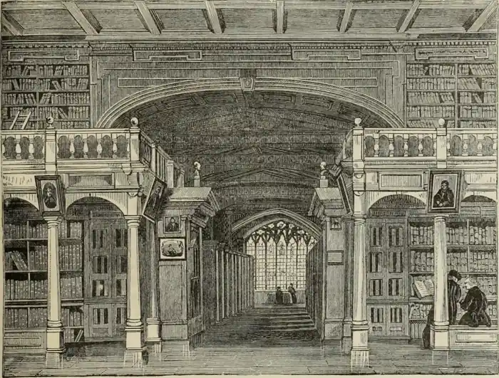

Read and listen together
 FrankensteinRead along